
1. Build the structure you will assess
Start a project, then add shapes from the drawing toolbar. A rectangle, wing or polygon is an editable part. Move it, set its dimensions and join it to its neighbours. For a drawn part, drag a corner to change its outline; double-click a wall to add a corner.
Our example combines a main hall, west and east wings, an angled entrance and a raised plant room. Its roofs stand at 8, 12 and 20 m above ground. A part’s height is its top above ground: a plant room rising 8 m above a 12 m roof has a top at 20 m.
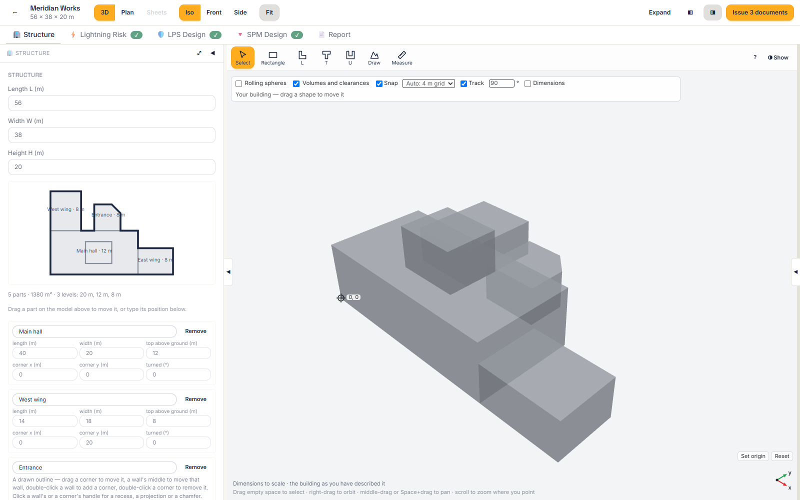
Use connected parts with flat roof levels. Courtyards, disconnected buildings, pitched surfaces and overhangs are outside this modelling workflow. Save the building before proceeding; the visible edit is not yet an issued engineering result.
2. Assess the risk and establish the protection decision
Open Lightning Risk. Establish the site and density source, then describe the structure’s relevant properties, services, risk zones and internal systems. Review every suggested value against the actual site. Save each section and compute.
Read each zone’s verdict against the tolerable risk, its contributing components and the projected result with measures. Where selected, inspect the frequency-of-damage assessment too. The working and assumptions are available on screen.
The protection decision has three possible outcomes: no LPS required by this assessment, a required class that achieves the criterion, or no available class that resolves the assessed risk. That last outcome needs further attention; it is not a class to carry into design.
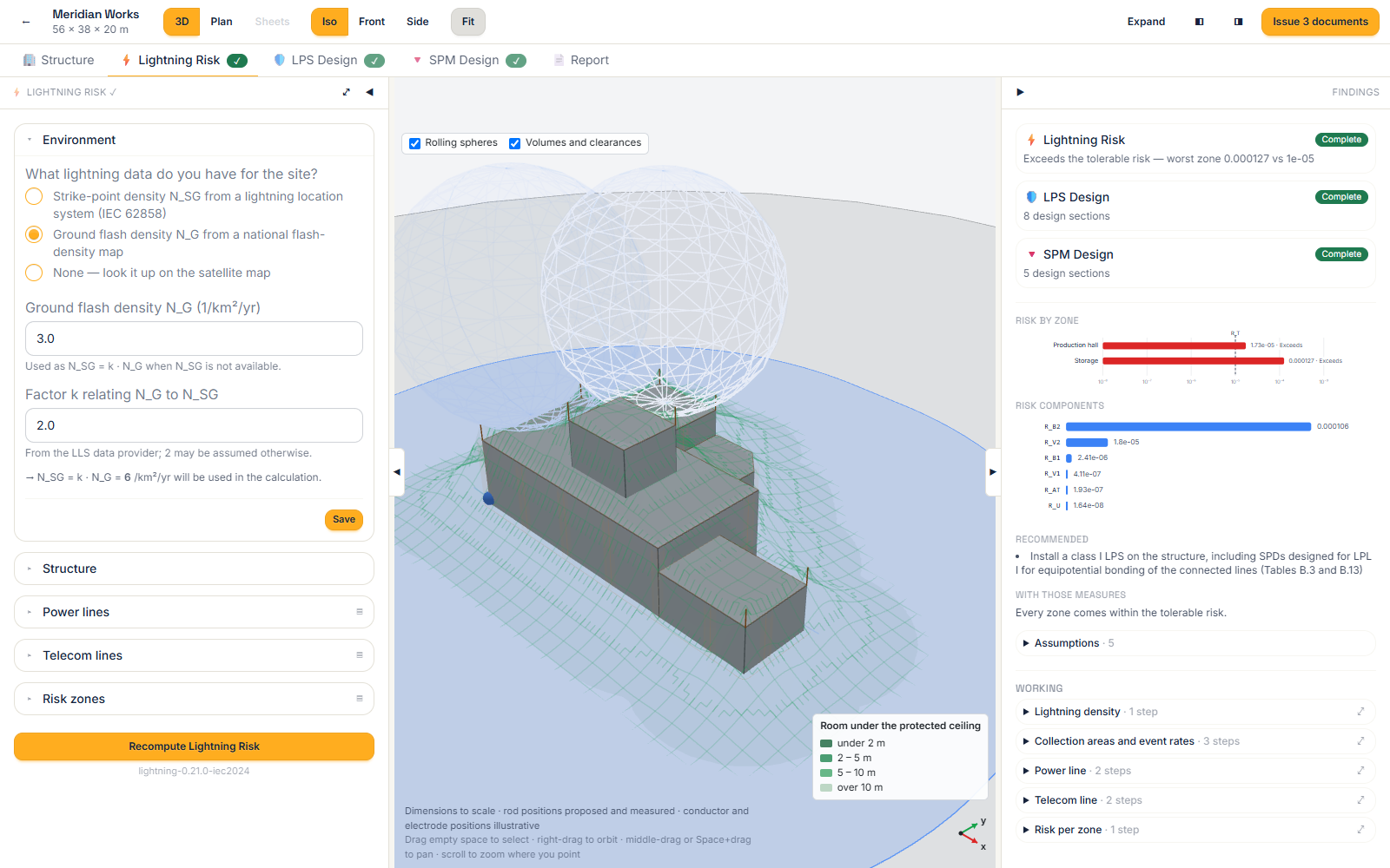
Understand the density source · Read about the 2024 assessment
3. Develop the external protection layout
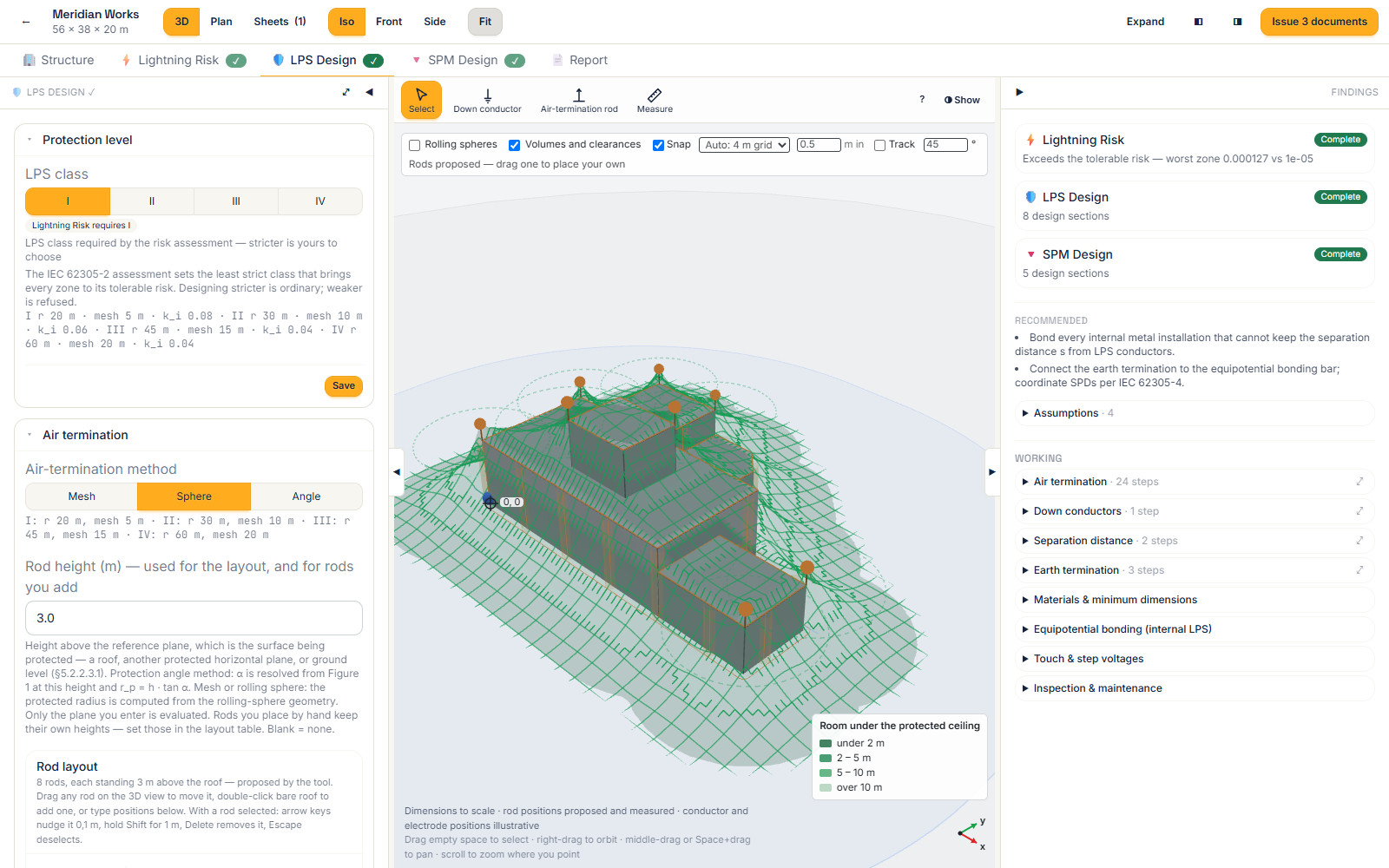
Open LPS Design on the same project. The risk assessment’s required class constrains the choice: a weaker class is refused. Review the class and select the air-termination method.
For a rod design, begin with a proposal or place your own rods. Edit positions and heights, and inspect each roof’s protection findings after saving and recomputing. Down-conductor positions can also be edited. A mesh design publishes conductor routes and lengths for the modelled roofs; it does not establish protection for every object above them.
Inspect the roof plan and sections alongside separation distance, earthing and the other design requirements. A proposed layout and a completed calculation do not replace checking construction details, rooftop obstructions and installation conditions.
4. Specify protection for services and equipment
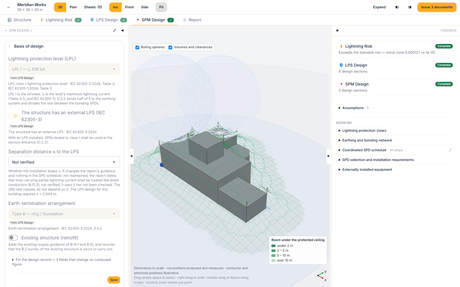
Open SPM Design and review the inherited protection basis. Define the supply and bonding arrangement, then the equipment groups and the services that feed them. A service can feed several groups; give each group the relevant withstand, distance and criticality.
Compute the schedule and inspect entrance and downstream requirements. Enter candidate SPD data to compare it with the schedule. Energy coordination between actual devices still needs manufacturer evidence; a successful numerical check alone does not establish it.
For equipment outside the structure, enter its position, height, installation conditions and feeder association. Suitable LPS rod data allows a check of its declared exposure. With no applicable layout or position, the declaration is not a geometric verification.
The handoff is selective. Building geometry and relevant computed facts are shared. Service lists and every study-specific answer are not automatically copied. Part 4 still needs its own electrical and installation information.
The shared basis has a source
These rows come directly from the sample dossier. The source study and clause travel with the value; the table is not a second set of calculations.
| Established | Value | By | Reference |
|---|---|---|---|
| Does the risk assessment require an LPS? | Yes | Lightning Risk | IEC 62305-2:2024, 7.3 (Figure 1) |
| LPS class required by the risk assessment | I | Lightning Risk | IEC 62305-2:2024, Table B.3, 7.3 |
| LPS class / lightning protection level | I | LPS Design | IEC 62305-3:2024, Table 2; IEC 62305-1:2024, Table 3 |
| The structure has an external LPS | Yes | LPS Design | IEC 62305-3:2024 |
| Required separation distance s (m) | 0.944 | LPS Design | IEC 62305-3:2024, 6.3 |
| Dangerous events N_D + N_L + N_DJ (1/yr) | 0.1516 | Lightning Risk | IEC 62305-2:2024, Annex A; read by IEC 62305-4 C.2.2 NOTE 1 |
| Metallic services modelled by the risk assessment | 2 | Lightning Risk | IEC 62305-2:2024, A.4; read by IEC 62305-4 C.2.6 |
5. Issue the document, then keep its history
Enter the project’s client, site address and named checker/approver, and your engineer details on the account. Review the Report panel, resolve stale results and issue the required study documents or dossier. Free access covers modelling, calculations and on-screen working; your own full documents require the corresponding paid access.
An issued report freezes its inputs, results and title block. Requesting the same unchanged issue returns that document. A changed result or title block creates a revision, with a reason required after the first issue. Named checker and approver fields record what you entered; they are not an electronic approval process.
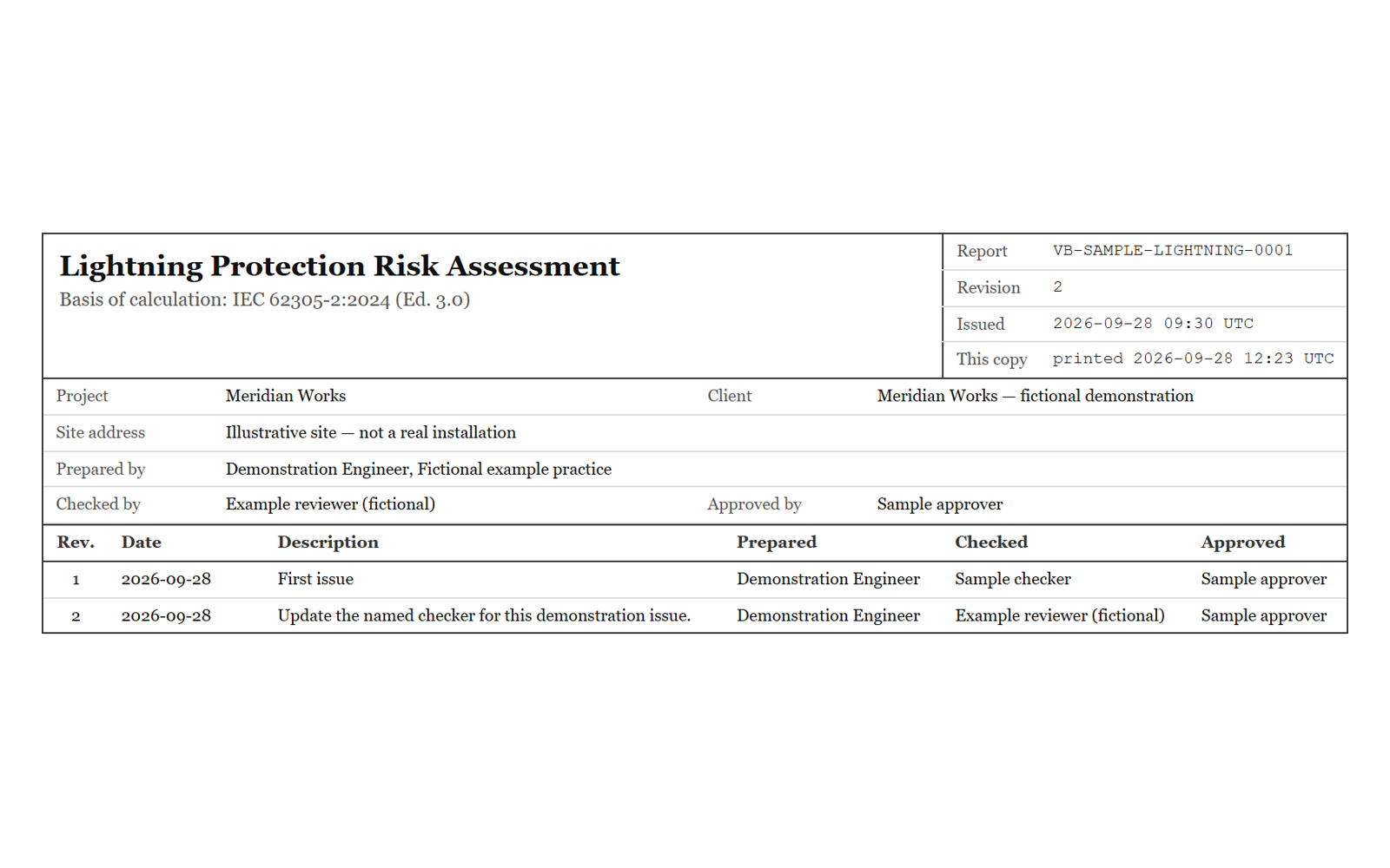
When the building changes: save the edit, recompute affected studies in order, review the resulting design and issue the revision. Changing an input can make results stale; issuing against moved inputs is refused. The combined dossier also identifies chapters that no longer describe the current building.
Meridian Works, its site and all named people are fictional demonstration data. The individual public study samples retain their separate worked examples. Use the relevant licensed standards and confirm the scope for your project; Voltbench supports the engineer of record’s judgement.